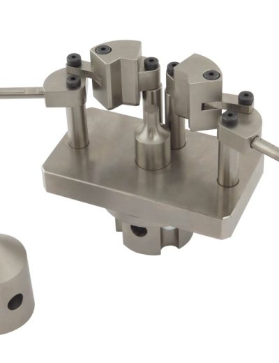
ASTM A185 Test Fixture
ASTM A185 covers welded wire reinforcement to be used for the reinforcement of concrete.
Please Contact With Us For More Information
ASTM A185 Standard Specification For Steel Welded Wire Reinforcement, Plain, for Concrete
ASTM A185 covers welded wire reinforcement to be used for the reinforcement of concrete.
NOTE 1—Welded wire for concrete reinforcement has been described by various terms: welded wire fabric, WWF, fabric, and mesh.
The wire reinforcement industry prefers the term “welded wire reinforcement” (WWR) as being more representative of the range of products being manufactured.
Therefore, the term “welded wire fabric” has been replaced with the term “welded wire reinforcement” in this specification and in related specifications
ASTM A185 / Weld Shear Test Apparatus and Methods
As the welds in welded wire reinforcement contribute to the bonding and anchorage value of the wires in concrete, it is imperative that the weld acceptance tests
be made in a jig that will stress the weld in a manner similar to which it is stressed in concrete.
In order to accomplish this the vertical wire in the jig must be stressed in an axis close to its center line.
Also the horizontal wire must be held closely to the vertical wire, and in the same relative position, so as to prevent rotation of the horizontal wire.
When the welded wire reinforcement is designed with different wire sizes, the larger diameter wire is the “vertical wire’’ when tested .
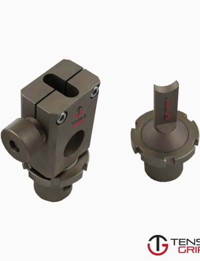
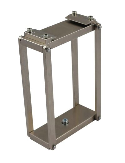
shows the details of a typical testing jig together with two anvils which make it possible to test welds for wire p to 15.88 mm (5⁄8 in.) in diameter.
This testing jig can be used in most tension testing machines and should be hung in a ball and socket arrangement at the center of the machine.
This, or a similarly effective fixture designed on the same principle, is acceptable.
Test specimens should be inserted through the notch in the anvil using the smallest notch available in which the vertical wire will fit loosely.
The vertical wire shall be in contact with the surface of the free rotating rollers while the horizontal wire shall be supported by the anvil on each side of the slot.
The bottom jaws of the testing machine shall grip the lower end of the vertical wire and the load shall be applied at a rate of stressing not to exceed
689 MPa/min (100 000 psi/min).
*** Before conducting ASTM A185 , it is important to read the entire specification. Standards can be obtained from appropriate standard authorities

